


LARGE FORMAT EQUIPMENT
(3) Toshiba and Union Large Format Boring Mills
(1) Dual Column Bridge Mill
(1) Millutensil Spotting Press
Up to 158” x 118” x 180″ table size
50 Ton Capacity
Our large format milling machines and spotting press allow us to produce massive bolsters, cassettes, and other large format tooling.
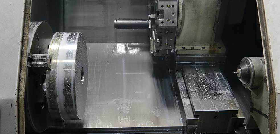
PRECISION CNC TURNING
(40) Okuma and Mazak CNC Lathes
Up to 6-jaw chucking capabilities
Live milling capabilities
Off-center radial and face cut features
Up to 24” diameter, 60” long
These lathes are making chips on all shifts with full part inspection, minimizing programming time and maximizing production efficiency.
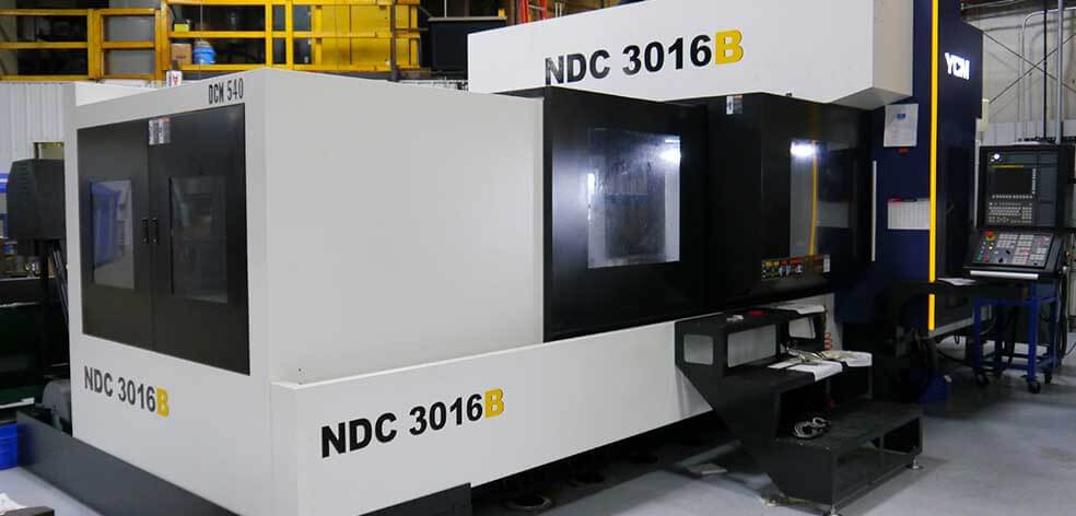
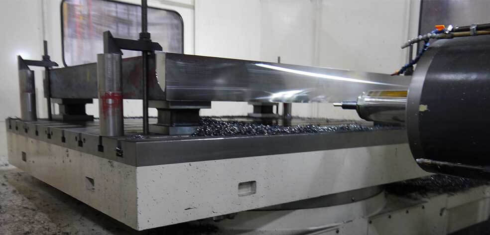
PRECISION CNC MILLING
(43) Okuma, Makino, and Mazak CNC Milling Machines
5-Axis and high-speed milling capability
Up to 55” x 47” x 55” horizontal table size
Up to 24” x 55” x 78” vertical table size
We combine deep machining know-how and unique work-holding fixtures to run our highly efficient and precise milling operation.
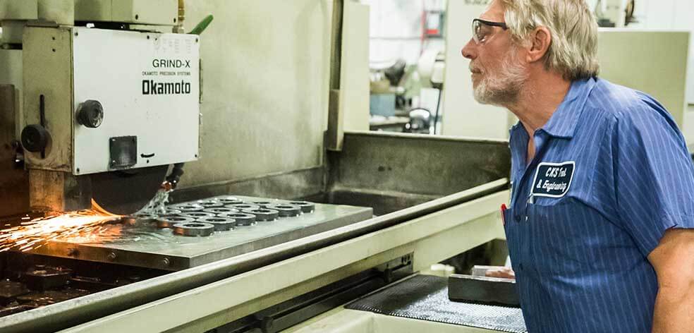
GRINDING AND HONING
(10) Okuma ID/OD Grinding and Sunnen Honing Machines
16” diameter, up to 40” long
(5) Okamoto Surface Grinders
20” x 40” table size
Our grind department is temperature and humidity controlled, allowing us to hold the tight tolerances your toughest project requires.
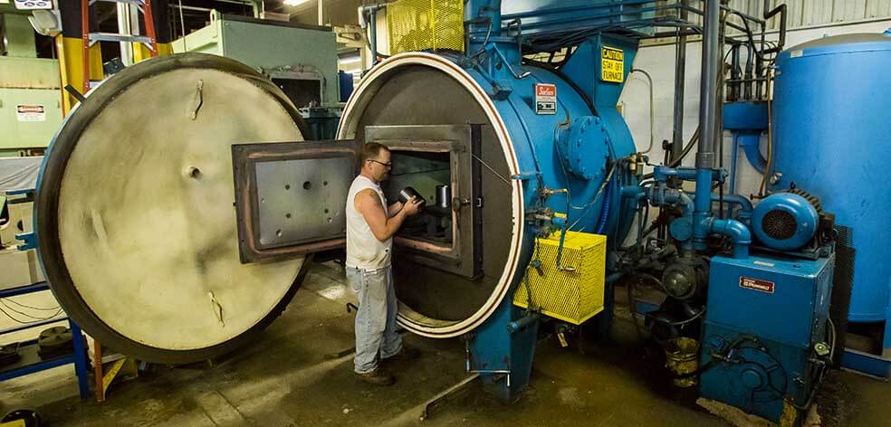
HEAT TREAT / BLACK OXIDE / CRYOGENICS
2,000 lb Carburizing Furnace
2 Bar Vacuum Furnace
Black Oxide Coating
Salt Pot
Fluidize Bed
Cryogenics
Compare our cryogenically treated and coated tools head-to-head against your existing tooling to see how much additional tool life you can achieve!
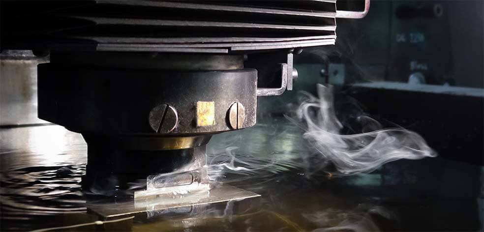
WIRE AND SINKER EDM
(5) Fanuc Wire EDM Machines
20” x 30” table size
(1) EDM Hole Burner
(2) Makino CNC Sinker EDM
98” x 55” x 32” table size
Our climate-controlled wire EDM department allows for small or odd-shaped angles and intricate contours.
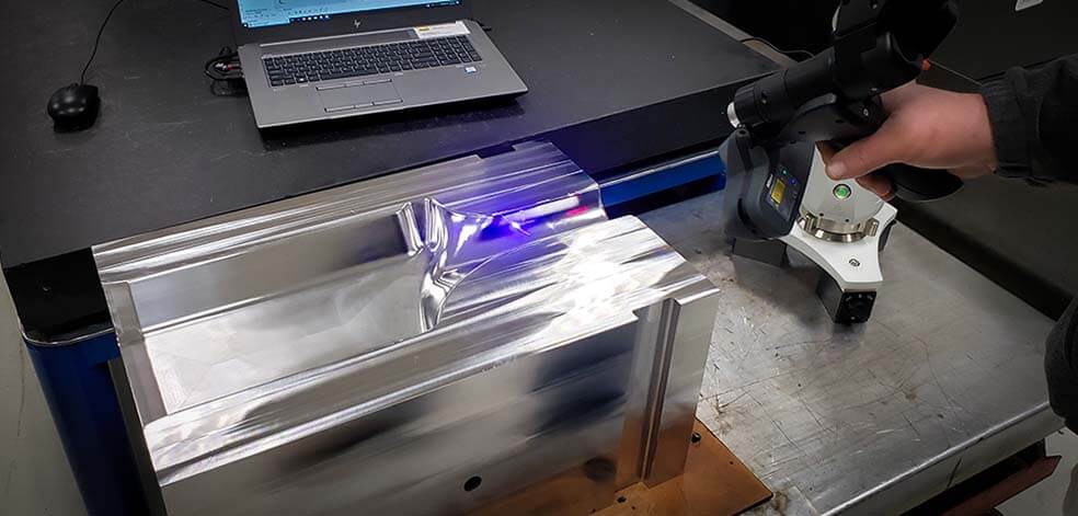
QUALITY & ENGINEERING
Inspection
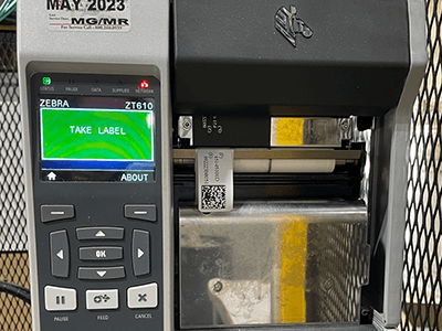
Part Marking
CAD/CAM
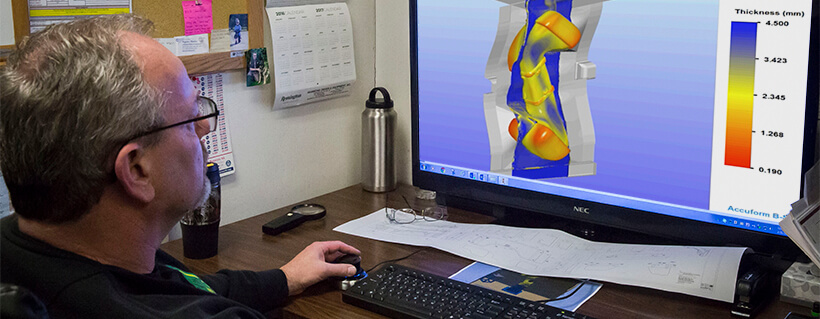
DEFORM Simulation
Our quality and engineering staff are armed with state-of-the-art equipment and receive ongoing training on critical inspection processes and capabilities.
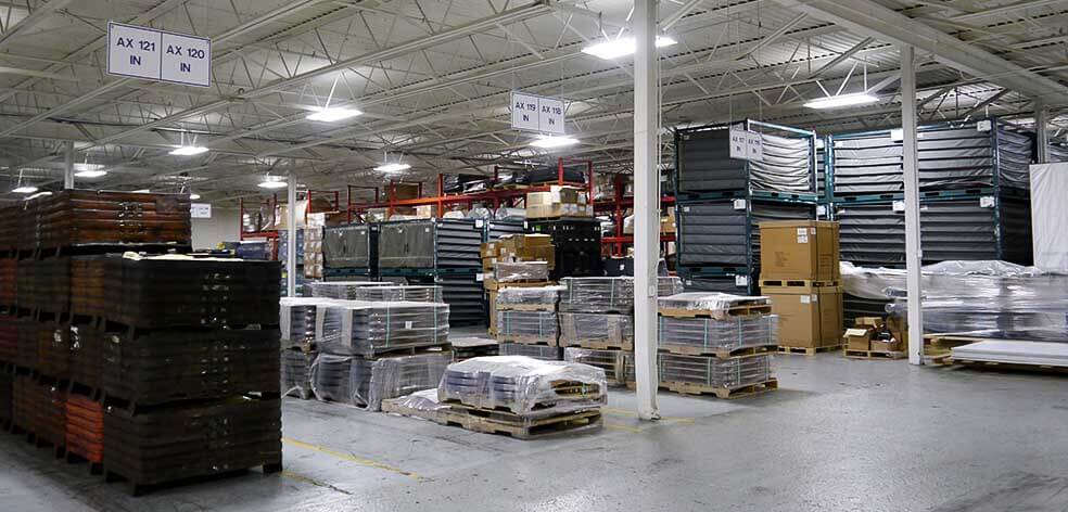
LOGISTICS
We maintain local logistics warehousing to accommodate incoming raw stock, as well as finished goods ready to ship.